2010 F250 Fuse Panel Diagram Wiper Motor
2010 Ford F150 Fuse Diagram
2010 Ford F150 Fuse Diagram
Ford F150 Fuse Diagram for Battery Junction Box and Smart Junction Box
This 2010 Ford F150 Fuse Box Layout post shows two fuse boxes; the Battery Junction Box/Power Distribution Box located under the hood and the Smart Junction Box/Passenger Compartment Fuse Panel
There's lots more information on this site for your vehicle.
To find fuse diagrams, click here
To find Relay locations, click here
To find Sensor Locations, click here
To find Module Locations, click here
To find Switch Locations, click here
To find Firing Order, click here
To find the most common trouble codes and fixes for your vehicle, click here
2010 Ford F150 Fuse Diagram for Battery Junction Box

2010 Ford F150 Fuse Box Layout for Battery Junction Box
11 30 Power Running Board (PRB) module
12 40 Cooling fan low speed relay
13 30 Starter relay
14 30 Seat control switch, passenger side front
15 40 Cooling fan high speed relay
16 – Not used
17 30 Trailer Brake Control (TBC) module
18 30 Upfitter relay 1
19 30 Upfitter relay 2
20 20 Transfer Case Control Module (TCCM)
21 30 Trailer tow battery charge relay
22 20 Cigar lighter, front
26 10 PCM power relay, Evaporative emission (EVAP) canister vent solenoid, 6R80 transmission
27 20 Fuel pump relay
28 10 Upfitter relay 4
29 10 Integrated Wheel End (IWE) solenoid
30 10 A/C clutch relay
31 20 Trailer tow parking lamp relay
32 40 Rear window defrost relay
33 – Not used
34 40 PCM power relay
35 – Not used
36 30 Anti-lock Brake System (ABS) module
41 15 Heated mirror relay
42 – Not used
43 20 Reversing lamp relay
44 15 Upfitter relay 3
45 20 Left and right trailer tow turn relays
46 15 Brake Pedal Position (BPP) switch
47 60 Anti-lock Brake System (ABS) module
48 – Not used
49 30 Windshield wiper motor
50 – Not used
51 40 Blower motor relay
52 – Not used
53 5 Powertrain Control Module (PCM), 6R80 transmission
54 5 Anti-lock Brake System (ABS) module, Transfer Case Control Module (TCCM) Digital
Transmission Range (DTR) sensor Trailer tow battery charge relay
55 5 Auto-dimming interior mirror unit, Rear view camera display mirror
56 – Not used
57 – Not used
58 15 Trailer tow connector – Reverse
59 – Not used
63 25 Cooling fan relay
64 30 Audio Digital Signal Processing (DSP) module
65 20 Power point, instrument panel
66 20 Power point, console 1 – with floor shifter
67 – Not used
68 20 Transfer Case Control Module (TCCM)
69 30 Dual Climate Controlled Seat Module (DCSM), Heated seat module
70 – Not used
71 – Not used
72 20 Power point, console 1 – with column shifter Power point, console 2 – with floor shifter
73 – Not used
74 30 Seat control switch, driver side front – without memory Driver Seat Module (DSM) – with memory
75 15 Powertrain Control Module (PCM)
76 20 Brake Pedal Position (BPP) switch, Mass Air Flow/Intake Air Temperature (MAF/IAT) sensor, Variable Camshaft Timing (VCT) solenoids, Heated oxygen sensors (HO2Ss), Evaporative emission (EVAP) canister purge valve, EGR system module, Intake Manifold Runner Control (IMRC)
77 10 Cooling fan relays, A/C clutch relay. Positive Crankshaft Ventilation (PCV) heated fitting, Floor shifter, Overdrive cancel switch
78 15 Coil on Plugs (COPs). Ignition transformer capacitors
79 10 Heated oxygen sensors (HO2Ss). 4R75 transmission
80 5 Steering wheel switches – illumination
81 – Not used
82 10 Trailer Brake Control (TBC) module
2010 Ford F150 Fuse Diagram for Smart Junction Box
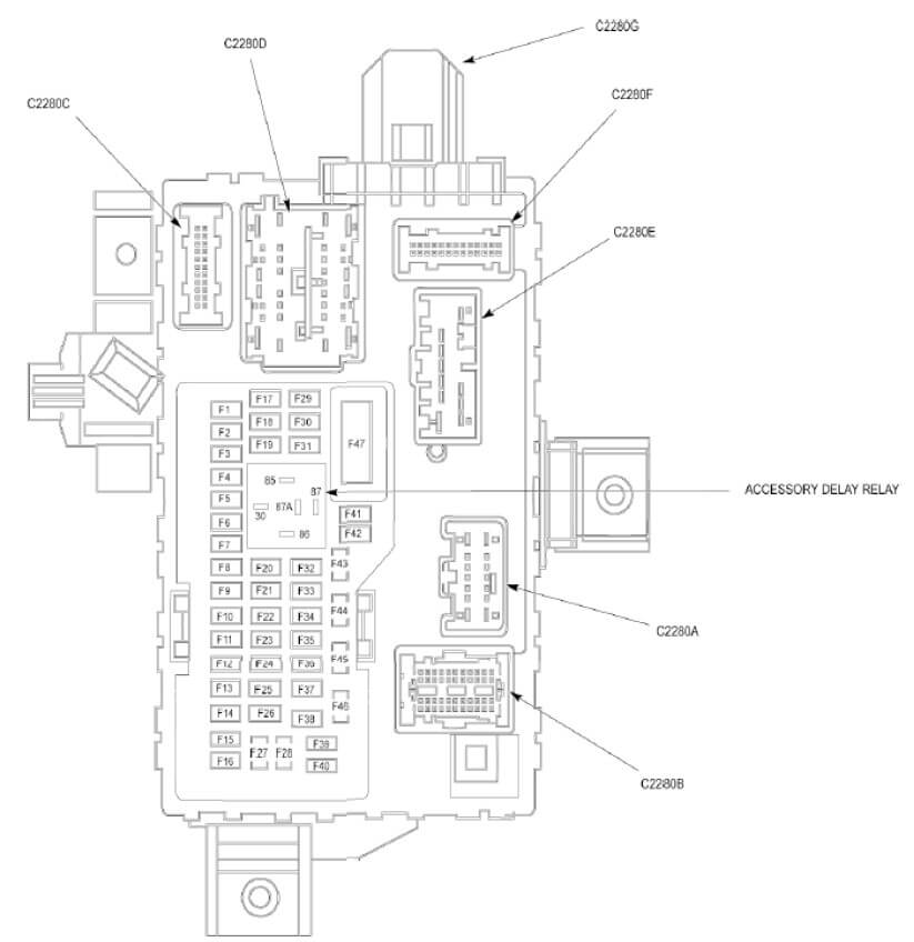
2010 Ford F150 Fuse Box Layout for Smart Junction Box
1 30 Roof opening panel module
2 15 Not used
3 15 Not used
4 30 Not used
5 10 Keyless entry keypad, Floor shifter, Brake shift interlock
6 20 Front park/turn lamps, Rear park/stop/turn lamps, Exterior rear view mirrors, Left and right trailer tow turn relays
7 10 Left headlamp – low beam
8 10 Right headlamp – low beam
9 15 Front and rear interior/map lamps assemblies, Front dome lamp, High mounted stoplamp
10 15 Exterior rear view mirrors, Backlighting
11 10 Global Positioning System Module (GPSM) – with SYNC
12 7.5 Exterior rear view mirror switch Driver Seat Module (DSM) – with memory
13 5 Accessory Protocol Interface Module (APIM)
14 10 Interior Lighting Control Module (ILCM)
15 10 HVAC module, EMTC – with manual a/c, HVAC module, DATC – with automatic a/c
16 15 Ignition switch
17 20 Door lock actuators
18 20 Seat control switch, driver side front
19 25 Not used
20 15 Data Link Connector (DLC), Adjustable pedal switch
21 15 Headlamp switch, Fog lamps
22 15 Front park/turn lamps, Front side lamps, Rear park/stop/turn lamps, License plate lamps, Front and rear marker lamps, High mounted stoplamp, Trailer tow parking lamp relay
23 15 Left and right headlamps – high beam
24 20 Horn, Horn switch
25 10 Front and rear interior/map lamps assemblies, Vanity mirror lamps, Tool link antenna module (in-dash computer with tool link), Front dome lamp
26 10 Instrument Cluster (IC), Key release interlock actuator, Front display interface module (FDIM) – without navigation, Front controls interface module (FCIM), Ignition switch
27 20 Not used
28 5 Audio Control Module (ACM) (without in-dash computer), In-dash computer
29 5 Instrument Cluster (IC)
30 5 Hazard/PAD/traction switch
31 10 Restraints Control Module (RCM)
32 10 Heated seat module, Electronic compass
33 10 Trailer Brake Control (TBC) module, Telematics module
34 5 Mode Select Switch (MSS), Off-road mode switch, Hill descent control switch
35 10 Parking Aid Module (PAM), Left rear heated seat module
36 5 Passive anti-theft transceiver
37 10 Upfitter switch
38 20 Subwoofer amplifier
39 20 Audio Control Module (ACM) (without in-dash computer), Front Display Interface Module (FDIM) – with navigation In-dash computer
40 20 Left rear heated seat module
41 15 Audio Control Module (ACM), Door lock switches, Auto-dimming interior mirror unit, Rear view camera display mirror
42 10 Not used
43 10 Rain sensor module, Rear view camera, Rear window defrost relay, Heated mirror relay
44 10 Not used
45 5 Blower motor relay, Windshield wiper motor
46 7.5 Occupant Classification System Module (OCSM)
47 30 c.b. Master window adjust switch, Passenger side window adjust switch, Overhead console switch assembly, Roof opening panel module
Source: https://ricksfreeautorepairadvice.com/2010-ford-f150-fuse-diagram/
Posted by: ededtallase0274401.blogspot.com

Post a Comment for "2010 F250 Fuse Panel Diagram Wiper Motor"